7 Best ways, how to choose carbide inserts
How to Identify Carbide Inserts and How to choose Carbide Inserts? This article will explain in detail through the following seven parts, which will surely provide you with valuable information.
1. Selection of Insert Shape
The shape of the insert relates to the workpiece material, the tool’s lead angle, nose angle, number of effective cutting edges, etc.
Different insert shapes have different nose strengths. Generally, the larger the nose angle, the greater the nose strength, and vice versa. Round inserts (R type) have the largest nose angle, while 35° diamond inserts (V type) have the smallest. When selecting, choose based on whether the cutting conditions are severe, targeting heavy, medium, or light cutting. When machine tool rigidity and power permit, large allowances and roughing should use inserts with larger nose angles. Conversely, for machine tools with low rigidity and power, small allowances, and finishing, inserts with smaller nose angles are suitable. Insert Shape vs. Nose Strength and Cutting Vibration
From the perspective of cutting forces, a larger nose angle results in a larger radial component force on the workpiece during machining, making it more prone to cause cutting vibration. Regarding the number of effective cutting edges, under the same conditions, round inserts have the most, while prismatic inserts have the fewest.

2. Selection of Insert Relief Angle
Common insert relief angles include N (0°), C (7°), P (11°), E (20°), etc. Generally, for roughing and semi-finishing, the N type can be used.
For semi-finishing and finishing, C type, P type, or N type inserts with chip breakers can be used.
For machining cast iron and hardened steel, the N type can be used.
For machining stainless steel, C type or P type can be used.
For machining aluminum alloy, P type, E type, etc., can be used.
For materials with good elastic recovery, a slightly larger relief angle can be selected.
Generally, for boring inserts, C type or P type are chosen; for large holes, the N type can be selected.
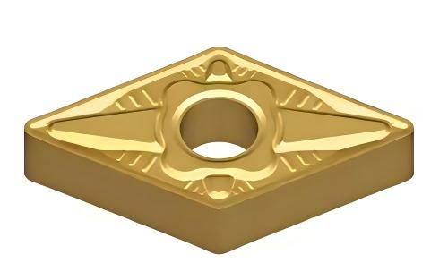
Let’s briefly understand CNC insert models through a specific example. Take the insert model DNMG150408-MS as an example. Its model contains rich information. This insert model consists of 10 positions. The first four letters represent the insert’s characteristics, while the following six numbers describe the insert’s dimensional model in detail. Each letter and number represents specific attributes, including shape, angles, and dimensions.
Specifically, D represents a 55° diamond insert, N indicates a relief angle of 0°, M denotes the insert’s manufacturing tolerance grade, and G describes the rake face type and center hole type. In the numerical part, 15 indicates a cutting edge length of 15 mm, 04 represents an insert thickness of 4.76 mm, and 08 indicates a nose radius of 0.8 mm.

Analysis of Each Component
Next, we further analyze each component of the insert model. Describing the specific meaning of each letter, such as shape code, relief angle, tolerance grade, as well as rake face and center hole type, helps clarify the significance of each detail. The first letter usually represents the shape of the CNC insert. Common shape codes include H, O, P, S, T, C, D, and E, representing regular hexagon, regular octagon, regular pentagon, square, rhombic (80° included angle), diamond (55° included angle), and diamond (75° included angle) respectively.
The second letter indicates the insert’s relief angle, where codes A to O correspond to different relief angle values, such as 3°, 5°, 7°, etc.
The third letter relates to the insert’s tolerance grade. Grade M and Grade G are the most commonly used tolerance grades. Grade M is typically suitable for roughing, semi-finishing, and finishing inserts, while Grade G is more often used for precision machining and super-hard inserts.
Finally, the fourth letter is used to describe the insert’s rake face type and center hole type (chip groove and hole). Through this detailed analysis, we can more clearly understand the meaning represented by each component of the CNC insert model.
3. Insert Tolerance Grade
Selection is based on the machining operation, such as finishing, semi-finishing, roughing, etc., to reduce machining costs while ensuring the task is completed.
3.1 In the ISO standard, tolerance is represented by letters, with Grade D representing the highest precision, followed by C, B, A, E, and F. The precision of Grade D tools can reach ±2 µm, suitable for high-precision machining. Grade C and B precision are within ±5 µm, suitable for general machining. Grade A, E, and F have relatively lower precision and are generally applied to simpler workpiece machining.
3.2 JIS (Japanese Industrial Standards) is the abbreviation for the organization setting Japanese domestic industrial standards. In the JIS standard, precision is also represented by letters, with Grade AA representing the highest precision, followed by A, B, C, D, and E. The precision of Grade AA tools can reach ±1 µm, suitable for high-precision machining. Grade A and B precision are within ±3 µm, suitable for general machining. Grade C, D, and E have relatively lower precision and are generally applied to simpler workpiece machining.
3.3 ASME (American Society of Mechanical Engineers) is the professional organization for American mechanical engineers. In the ASME standard, precision is also represented by letters, with Grade AA representing the highest precision, followed by A, B, C, D, and E. The precision of Grade AA tools can reach ±1 µm, suitable for high-precision machining. Grade A and B precision are within ±3 µm, suitable for general machining. Grade C, D, and E have relatively lower precision and are generally applied to simpler workpiece machining.
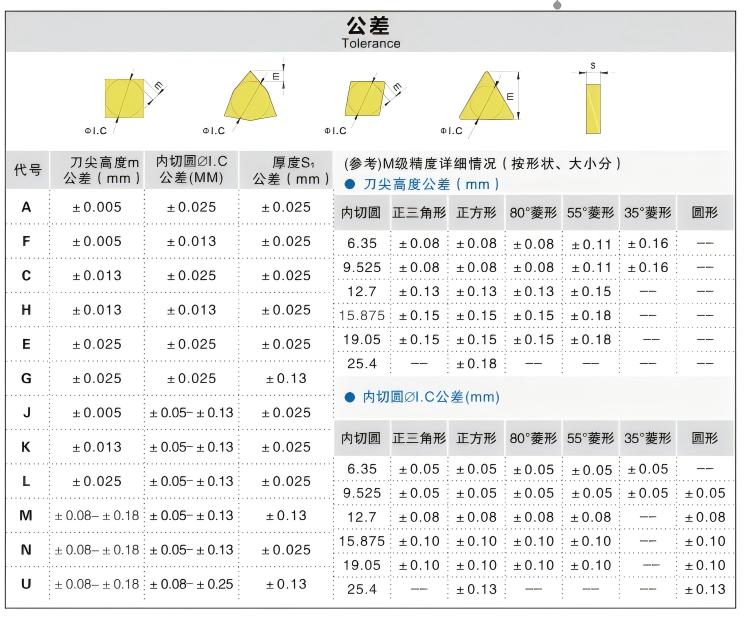
3.4 Chinese Standard has 12 tolerance grades from A to U. Grades G, M, and U are commonly used for turning. Generally, high-precision Grade G inserts are selected for precision machining; for non-ferrous metals finishing and semi-finishing, Grade G inserts are suitable. Finishing of hardened steel (above 45 HRC) can also use Grade G inserts. Finishing to heavy-duty roughing can use Grade M inserts; roughing can use Grade U inserts.
3.5 Conclusion Letters representing CNC tool precision include standards like ISO, JIS, and ASME. Among them, Grade D and AA represent the highest precision, Grade A and B are suitable for general machining, and Grade C, D, and E are suitable for simpler workpiece machining. Different letter standards apply to different machining requirements. Selecting tools with standard precision can improve machining efficiency and quality.

4. Nose Radius
It not only affects cutting efficiency but also relates to the machined surface roughness and precision. Considering the relationship between nose radius and maximum feed rate, the maximum feed should not exceed 80% of the nose radius dimension. Otherwise, cutting conditions will deteriorate, potentially leading to threaded surface marks and tool breakage. Therefore, the selected nose radius should be equal to or greater than 1.25 times the maximum feed rate for the part turning. When the nose angle is less than 90°, the allowable maximum feed rate should be reduced.
Nose radius is also related to chip breaking reliability.
To ensure chip breaking, there is a minimum value for cutting allowance and feed rate. When the nose radius decreases, these two minimum values also decrease accordingly. Therefore, for reliable chip breaking, small nose radii are typically used for small-allowance, low-feed turning operations, while larger nose radii are suitable for the opposite.
Geometrically, nose radius and feed rate are the two parameters forming the surface roughness of the machined part: h ≈ f² / (8 * rε) (where h is the machined surface profile height in µm, f is the feed rate in mm/rev, and rε is the nose radius in mm). From this formula, once the required machined part surface roughness and feed rate are set, the corresponding nose radius can be selected: rε ≥ f² / (8 * h).
5. Selection of Chip Breaker Groove Type
Chip breaker groove types for carbide inserts produced in China are divided into two main categories. The first category comprises 23 groove types recommended by the national standard (GB 2076-1987). The second category includes groove types with corresponding applicable ranges recommended in the product catalogs of China’s two major carbide manufacturers. It is impossible to list all dozens of groove types from these two categories; relevant catalogs can be consulted for selection. For conventional CNC machining, insert chip breaker grooves have developed towards two modes: basic groove types plus supplementary groove types. That is, covering the widest possible machining range with the smallest number of basic grooves, supplemented by other groove types to fill the gaps. The groove type is determined based on the machining operation type and the material properties of the workpiece. Representation methods vary by supplier, but the basic approach is similar: basic groove types are categorized by operation type as Finishing (code F), Medium/General machining (code M), and Roughing (code R).
6. Selecting Insert Type Based on Workpiece Material
According to international standards, there are types for Steel (P class), Stainless steel & Alloy steel (M class), and Cast iron (K class). Combining these two aspects gives the corresponding groove types. For example, PF refers to a groove type for finishing steel, KM is for general machining of cast iron, etc. If machining extends towards two directions, such as ultra-finishing and heavy roughing, and materials also extend, such as heat-resistant alloys, aluminum alloys, non-ferrous metals, etc., supplementary groove types for ultra-finishing, heavy roughing, and machining heat-resistant alloys, aluminum alloys, etc., become available. Specific product catalogs should be consulted for selection.
7. Insert Brand Selection
This refers to selecting the tier/grade of the tool. The choice of tool tier is closely related to the grade of the machine tool, the requirements of component machining, product value, the type of enterprise, and the market status of the enterprise’s products. Currently, within the Chinese tool industry, there is a perception of the “hierarchy” of tool origins:
(1) Germany,
(2) Europe/America, Israel, Japan
(3) Korea, China.
Our company is among China’s top ten cemented carbide manufacturers. Should you require cemented carbide products, please contact us.
